
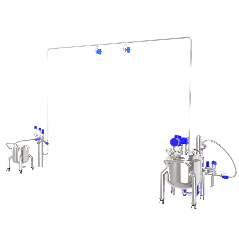
Air Control Unit (ACU)
Ensuring the safe storage of materials
Ensuring safe material storage while balancing material transfer efficiency between upstream and downstream production lines.


Product Characteristics

Environmental Protection
The integrated blower function prevents material dust from dispersing into the environment.

Flexibility
Modular design facilitates easy disassembly and assembly, allowing flexible upgrades based on material characteristics.

Free from Maintenance
Equipped with a jet-type self-cleaning filter element, requiring no frequent replacement, and utilizes high-quality blowers for extended service life.

High Applicability
Supports customization of material, capacity, filtration precision, conveying accessories, and auxiliary functions.
Technical Parameters
| Name | Parameters |
| Equipment Name | Air Control Unit |
| Dust Collection Fan | 1.1KW |
| Vibrating Fan | 0.12KW |
| Air Supply Pressure | 0.4-0.6MPA |
| Air Consumption of the Compressor | 20L/MIN |
| Supply Voltage | 380V |
Maintenance and Services
of the Air Control Unit
Other products
-
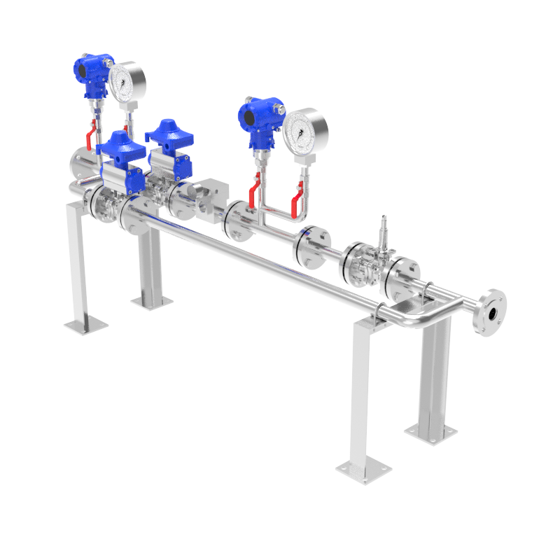
Pigging Ball System
It is a technology that utilizes compressed air, nitrogen, water etc. as a driving force to propel the pig through the pipeline, achieving residual material recycling and pipeline cleaning.
-
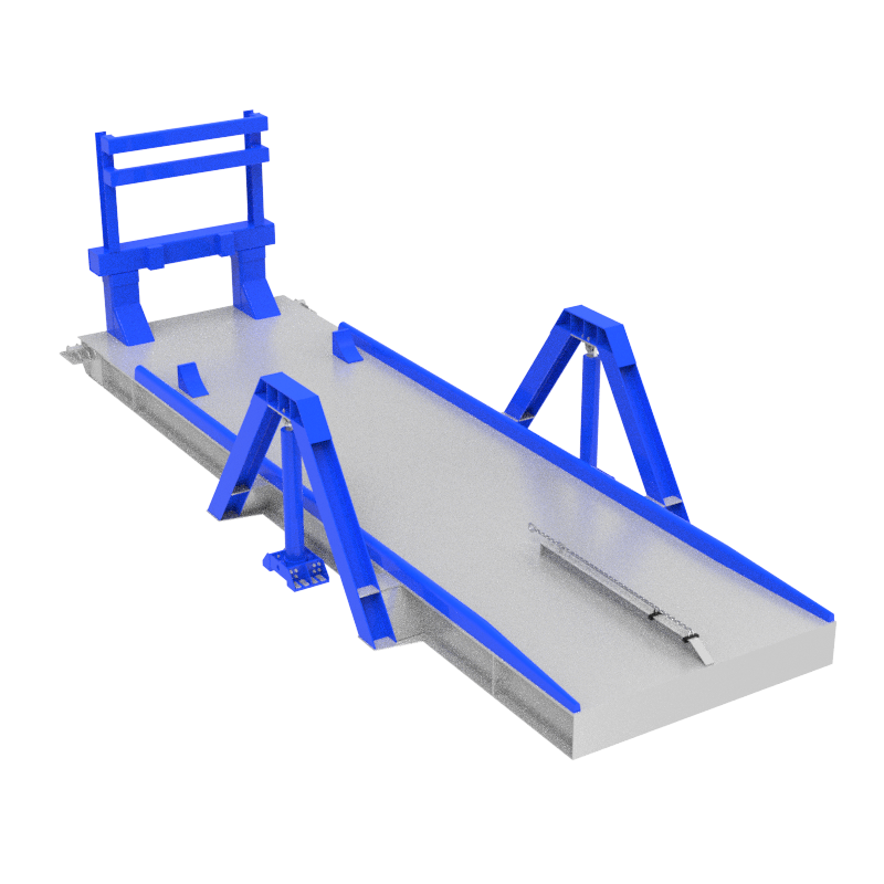
Container Unloading Platform
Ensuring safe material storage while balancing material transfer efficiency between upstream and downstream production lines.
Expert Consultation Portal
Assisting you in formulating industrial upgrade plans


Committed to becoming
a world-leading service provider
of material handling technologies

Contact information
Leave your contact information and a dedicated consultant will get in touch with you as soon as possible.


